Matías Ramos MD.1,*, Roberto Orofino Giambastiani MD.2, Diego Riva Eng3, María Fernanda Biancolini MD.4, Ignacio Lugones MD PhD.5
 ORCID
ORCIDRecibido: 21-10-2021
Aceptado: 08-01-2021
©2022 El(los) Autor(es) – Esta publicación es Órgano oficial de la Sociedad de Anestesiología de Chile
Revista Chilena de Anestesia Vol. 51 Núm. 4 pp. 404-413|https://doi.org/10.25237/revchilanestv5111051509
PDF|ePub|RIS
Modelo electrónico basado en computadora de ventilación combinada utilizando un nuevo dispositivo médico
Abstract
The increased demand for mechanical ventilation caused by the COVID-19 pandemic could generate a critical situation where patients may lose access to mechanical ventilators. Combined ventilation, in which two patients are ventilated simultaneously but independently with a single ventilator has been proposed as a life-saving bridge while waiting for new ventilators availability. New devices have emerged to facilitate this task and allow individualizaron of ventilatory parameters in combined ventilation. In this work we run computer-based electrical simulations of combined ventilation. We introduce an electrical model of a proposed mechanical device which is designed to individualize ventilatory parameters, and tested it under different circumstances. With an electronic circuit simulator applet, an electrical model of combined ventilation is created using resistor-capacitor circuits. A device is added to the electrical model which is capable of individualizing the ventilatory parameters of two patients connected to the same ventilator. Through computational simulation, the model is tested in different scenarios with the aim of achieving adequate ventilation of two subjects under different circumstances: 1) two identical subjects; 2) two subjects with the same size but different lung compliance; and 3) two subjects with different sizes and compliances. The goal is to achieve the established charge per unit of size on each capacitor under different levels of end-expiratory voltage (as an end-expiratory pressure analog). Data collected included capacitor charge, voltage, and charge normalized to the weight of the simulated patient. Simulations show that it is possible to provide the proper charge to each capacitor under different circumstances using an array of electrical components as equivalents to a proposed mechanical device for combined ventilation. If the pair of connected capacitors have different capacitances, adjustments must be made to the source volt- age and/or the resistance of the device to provide the appropriate charge for each capacitor under initial conditions. In pressure control simulation, increasing the end-expiratory voltage on one capacitor requires increasing the source voltage and the device resistance associated with the other simulated patient. On the other hand, in the volume control simulation, it is only required to intervene in the device resistance. Under simulated conditions, this electrical model allows individualization of combined mechanical ventilation.
Resumen
La mayor demanda de ventilación mecánica provocada por la pandemia de COVID-19 podría generar una situación crítica en la que los pacientes podrían perder el acceso a ventiladores mecánicos. La ventilación combinada, en la que dos pacientes son ventilados simultáneamente, pero de forma independiente con un solo ventilador se ha propuesto como un puente para salvar vidas mientras se espera la disponibilidad de nuevos ventiladores. Han surgido nuevos dispositivos para facilitar esta tarea y permitir la individualización de los parámetros ventilatorios en la ventilación combinada. En este trabajo realizamos simulaciones eléctricas por computadora de ventilación combinada. Presentamos un modelo eléctrico de un dispositivo mecánico propuesto que está diseñado para individualizar los parámetros ventilatorios y lo probamos en diferentes circunstancias. Con un programa simulador de circuitos electrónicos, se creó un modelo eléctrico de ventilación combinada utilizando circuitos resistor-capacitor. Se añadió al modelo eléctrico un dispositivo que es capaz de individualizar los parámetros ventilatorios de dos pacientes conectados a un mismo ventilador. Mediante simulación computacional, el modelo se prueba en diferentes escenarios con el objetivo de lograr una ventilación adecuada de dos sujetos en diferentes circunstancias: 1) dos sujetos idénticos; 2) dos sujetos con el mismo tamaño, pero diferente distensibilidad pulmonar; y 3) dos sujetos con diferentes tamaños y distensibilidad. El objetivo es lograr la carga establecida por unidad de tamaño en cada capacitor bajo diferentes niveles de voltaje al final de la espiración (como un análogo a la presión al final de la espiración). Los datos recopilados incluyeron la carga del capacitor, el voltaje y la carga normalizada al peso del paciente simulado. Las simulaciones muestran que es posible proporcionar la carga adecuada a cada capacitor en diferentes circunstancias utilizando una matriz de componentes eléctricos como equivalente a al dispositivo mecánico propuesto para la ventilación combinada. Si el par de capacitores conectados tienen diferentes capacitancias, se deben realizar ajustes en el voltaje de la fuente y/o la resistencia del dispositivo para proporcionar la carga adecuada para cada capacitor. En la simulación de presión control, aumentar el voltaje al final de la espiración en un capacitor requiere aumentar el voltaje de la fuente y la resistencia del dispositivo asociado con el otro paciente simulado. Por otro lado, en la simulación de volumen control, solo se requiere intervenir en la resistencia del dispositivo. Bajo las condiciones simuladas, este modelo eléctrico permite la individualización de la ventilación mecánica combinada.
-
Introduction
Acute respiratory distress syndrome caused by COVID-19 increased the demand for mechanical ventilation world- wide [1]. An imbalance between supply and demand for ventilators could pose a critical scenario in which it would be necessary to decide which patients have to be assigned to these devices and which ones not[2],[3],[4].
Combined ventilation has been postulated as a strategy to face this problem[5],[6]. Although this setup may be simple in principle, the dynamics of two patients connected to the same ventilator may require deep understanding of advanced concepts related to mechanical ventilation. This fact has led some scientific societies to disencourage this configuration. One of the strongest arguments against this arrangement is the inability to personalize ventilatory parameters for each patient[7].
As interest in combination ventilation increased, the need to configure parameters individually for each patient led to the creation of different devices that facilitated the task. DuplicAR® is one of these devices that allows simultaneous and independent ventilation of two subjects with only one ventilator [8]. The goal of this device is to enable mechanical ventilation of two patients with a single ventilator, without cross-contamination, and allowing for independent management of the inspiratory pressure (Pi) and positive-end expiratory pressure (PEEP). In this work we propose an electrical simulation model of combined ventilation and the in silico test of the DuplicAR® device.
-
Materials and Methods
-
Systems to combine ventilation
Although combined ventilation can be implemented with a particular configuration of the inspiratory and expiratory tubes, in the last year, different devices have emerged that facilitate implementation and add setting possibilities to each individual under combined mechanical ventilation. DuplicAR® is a medical device which functions as a complementary adapter to the mechanical ventilator and provides a mechanism to offer ad- equate and independent pressurization of the system for the two subjects. It consists of a device with two “Y” pieces and regulators embedded in its structure. The inspiratory adapter connects to the inspiratory port of the ventilator and to each subject’s inspiratory line (Figure 1A). Each inspiratory line can control the inspiratory pressure through a diameter (i.e. resistance) regulator that allows independent management of the tidal volume (Vt). The expiratory adapter connects to each subject’s expiratory line and to the expiratory port of the ventilator. Each expiratory line has a positive end-expiratory pressure (PEEP) controller for independent management of this variable. Cross-contamination is prevented through one-way valves and microbiological filters in each line of the circuit.
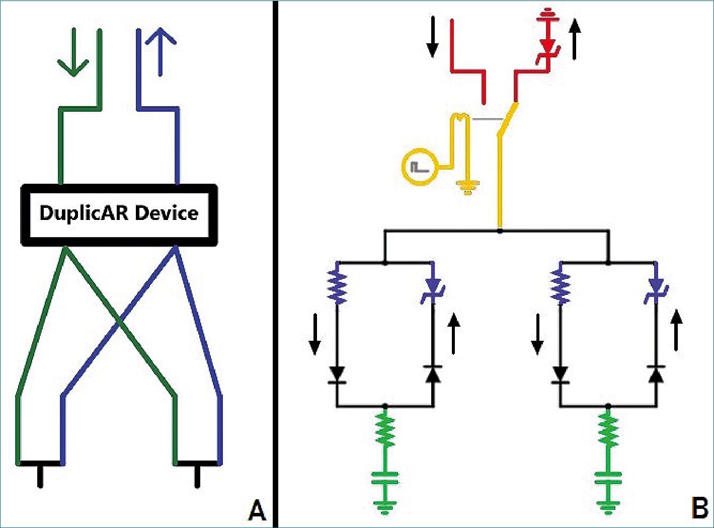
Figure 1. A. The DuplicAR® device: sche- matic drawing (green: inspiratory lines; blue: expiratory lines; arrows: ventilator ports); B. Electrical diagram of combined ventilation: in red, the “ventilator system”; in green, the “subject system”; in yellow, the connection between both systems through the relay; in blue, the DuplicAR® system. The black arrows outside the circuit represent the direction of the current.
-
Electrical model simulation
The code to reproduce the circuits used in the simulations with the corresponding instructions can be found in the supplementary material or in the following link (circuit schematics).
Nota: Este es el link del hipervínculo en “circuit schematics”: https://www.notion.so/mattplate/Electronic-Computer-Based- Model-of-Combined-Ventilation-Schematics-of-Circuits-4fe- 0faf4b4c7498c814ca18699bc1a1c
Our electric combined ventilation model is made up of two systems: the “ventilator system” and the “subject system” (Figure 1B). The ventilator system includes a constant voltage or current (depending on simulated ventilation mode) and a ground connection. The first is a power source which represents the inspiratory part of the ventilator, while the second represents the expiratory part. The subject system is represent- ed by a series connection of an electrical resistance and a capacitor (RC circuit).
The connection between both systems is achieved through a relay. The relay is a device that works as a switch triggered by an external circuit. The current from the external circuit passes through a coil generating a magnetic field that moves the switch of the relay. In this way, the switch moves from the power source to ground in a cyclical manner, governed by the current in its external circuit. By manipulating the current in the external circuit, the behavior of the relay can be controlled. Thus, a ventilatory cycle is simulated by a current pulse in the external circuit that moves the switch (relay) to the power source and then at the end of the pulse, back to ground. The percentage of the cycle that the external circuit source maintains the voltage across the coil (and therefore the switch on “inspiration”) is determined by the “active cycle” of the relay. For example, if the active cycle is set to 33%, and an I:E ratio of 1:2 is simulated. The ventilatory rate is represented by the pulse
rate. As the “inspiratory port” has a constant voltage source, the system represents the pressure control mode of mechanical ventilation (PCV). When a constant current source is used, the system represents volume control ventilation (VCV). The flows in the inspiratory and expiratory lines are directed by diodes.
To simulate the PEEP, a Zener diode with modifiable break- down voltage is added prior to grounding the expiratory port. The Zener is a special type of diode that always allows cur- rent to flow in one direction, but only allows it in the opposite direction if a certain voltage threshold is exceeded (known as “breakdown voltage”). By setting a zero breakdown voltage, the diode behaves like a simple conductor. Setting a nonzero breakdown value, the diode will “catch” that voltage from “behind” and not allow current to flow to ground. Thus, the Zener diode functions as the equivalent of a PEEP valve. Images and video clips of the simulations can be found in the supplementary material section.
A theoretical weight is established for each simulated subject. Although weight is not a variable to consider in electric models, in this system we consider weight as the value that determines the amount of charge suitable for the RC circuit. The objective in each simulation is to load that RC circuit with the charge that we consider convenient according to the simulated weight. This normalized charge is chosen at 7 pC kg-1, a value that is numerically equal to the 7 ml kg-1 that could be used as the tidal volume in real mechanical ventilation. On the other hand, assuming the size of the lung correlates with the size of the individual, we use weight to normalize capacitance to lung size.
Given the “fast” nature of electrical phenomena, the basal cycling frequency of the ventilator system is set at 45 Hz and the active cycle at 33.33%, generating cycles of 22.2 ms (1000ms/45) and “inspiratory times” of 7.39 ms (0.33 x 22.2). Given the RC circuit characteristics of the simulated subjects, at least 10 expiratory time constants are allowed to take place with this configuration to ensure no charge trapping. This cycling frequency is considered equivalent (in mechanical ventilation) to a respiratory rate of 10 to 12 ventilations per minute in patients with normal resistance and compliance (Table 1)[9].
Table 1. Equivalences between the mechanical and electrical models
| Variable | Real model | Electrical equivalent |
| Weight | 50 kg | 50 kg |
| Target volume or charge | 7 ml/kg | 7 pC/kg |
| Compliance or capacitance | 30 ml/cmH2O | 30 pF |
| Resistance | 14 cmH2O / l/s | 40 Q |
| Cycle frequency | 10 / minute | 45 Hz |
| Inspiration | 2 s | 7.39 ms |
| Expiration | 4 s | 14.81 ms |
| I:E Ratio | 1:2 | 1:2 |
| Time constant (t) | 0.42 s | 1.2 ms |
| t allowed in expiration | 9.5 | 12.3 |
Combined ventilation model involves placing two “patient systems” (ie. two RC circuits) in parallel with a single power source.
The DuplicAR® system is simulated with a variable resistor in the inspiratory line and a Zener diode in the expiratory line of each subject (Figure 2, in blue).
By adjusting the electrical resistance of the DuplicAR® system, we control the voltage received by that “patient
system”. The concept of increasing inspiratory resistance to regulate tidal volume is not new and has been implemented for differential ventilation of the lungs of the same patient. In its most basic form, the concept of ventilating two lungs in parallel or two patients in parallel is the same[10]. Adjusting the Zener breakdown voltage of the DuplicAR®, we control the end-expiratory voltage (EEV, equivalent to end-expiratory pressure).
The electrical simulations are performed in Falstad Circuit Simulator 2.2.13js, a Java-based electronic simulator[11]. Equivalences between models are shown in Table 1.
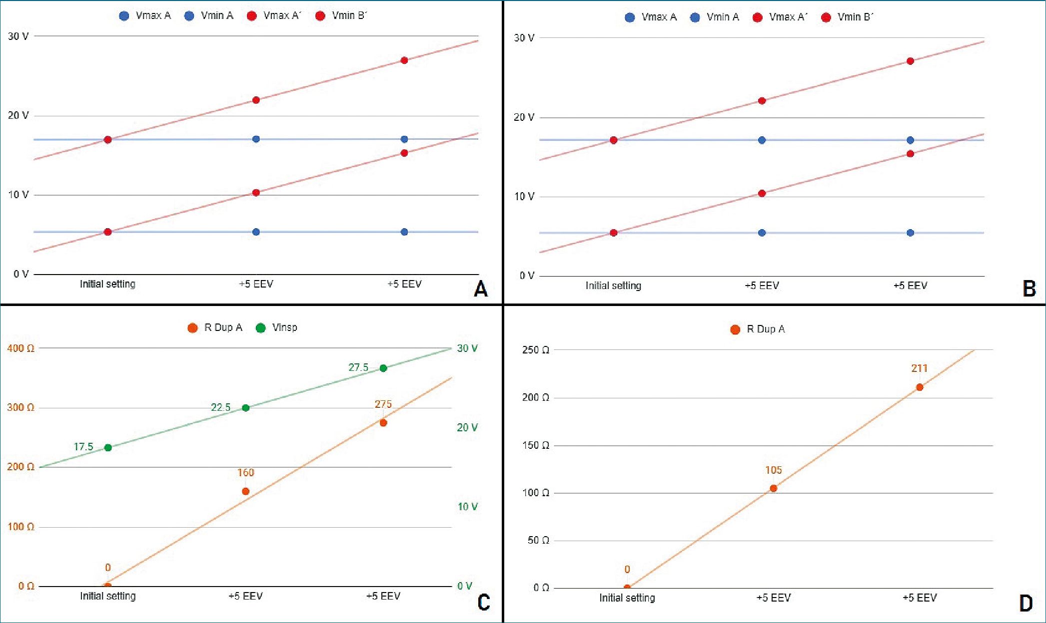
Figure 2. Stage 1 simulation A. Voltages registers under PCV mode; B. Voltages registers under VCV mode; C. PCV mode. In green, power source voltage; in orange DuplicAR® resistance of one RC circuit; D. VCV mode. DuplicAR® resistance of one RC circuit in each step.
-
Experimental Setting
Three patient models are simulated, each with particular characteristics of weight and compliance.
Subject (RC circuit) A: 50 kg weight, 30 pF capacitance (0.6 pF/kg).
Subject (RC circuit) B: 50 kg weight, 20 pF capacitance (0.4 pF/kg).
Subject (RC circuit) C: 28 kg weight, 10 pF capacitance (0.35 pF/kg).
All subjects/circuits have 40 Q resistance.
The simulations are run in three different stages, which are recreated by connecting two RC circuits to the same ventilator system and tested under PCV and VCV modes:
Stage 1: Two identical RC circuits (A and A), representing identical subjects.
Stage 2: Two RC circuits (A and B), representing subjects of the same size but different compliances.
Stage 3: Two RC circuits (A and C), representing subjects of different size and compliances.
The initial ventilator setting is configured as follows: 45 Hz of cycling frequency, an I:E ratio of 1:2 and a Zener breakdown voltage of 5 V. In PCV, the inspiratory voltage is configured to ensure charging with 7 pC kg-1 each RC circuit. In VCV an inspiratory current is configured in such a way that, given the Ti, the power source delivers the necessary charge to achieve 7 pC kg-1 in each RC circuit.
Once ventilation is established, successive 5 V increments are made on the EEV in one RC circuit through manipulation of the Zener diode of the DuplicAR® system. First, voltage is incremented to 10 V of EEV and then up to 15 V, maintaining the initial EEV (5 V) in the contralateral RC circuit and always guaranteeing the same charge of 7 pC kg-1 in both. To achieve the objective of the initial configuration and of guaranteeing the 7 pC kg-1 for each RC circuit despite the EEV increments, the settings of the DuplicAR® system and/or in the ventilator are adjusted. The data are tabulated and recorded in a spreadsheet for this purpose.
The three stages are summarized in Table 2.
Table 2. Summary of the 3 stages, with the characteristics of each subject, initial setting of the ventilator and target charge for each subject
| Stage 1
A A |
Stage 2
A B |
Stage 3
A C |
||
| Size (kg) | 50 | 50 | 50 28 | |
| Capacitance (pF) | 30 | 30 20 | 30 10 | |
| Resistance (Q) | 40 | 40 | 40 | |
| Capacitance/size (pF/kg) | 0,6 | 0.6 0.4 | 0.6 0.35 | |
| Initial settings | ||||
| Inspiratory voltage – PCV (V) | 17.5 | 23.3 | 25.4 | |
| Inspiratory current – VCV (mA) | 94.5 | 94.5 | 73.7 | |
| I:E | 1:2 | 1:2 | 1:2 | |
| Cycle frequency (Hz) | 45 | 45 | 45 | |
| Target load/size (pC/kg) | 7 | 7 | 7 | |
| Target charge (pC) | 350 | 350 | 350 196 | |
| Initial EEV (V) | 5 | 5 | 5 | |
-
Results
Tables with simulation data for each stage can be found in the supplementary material.
Stage 1
It is first evidenced that, without manipulation of the DuplicAR® device, the voltage difference in each capacitor is the same (11.64 ± 0.03 V), and therefore its charge is also the same (349.28 ± 0.85 pC). Charge on each capacitor is calculated acording to.
q. .
In both ventilatory modes, PCV and VCV, it is possible to modify the EEV of one RC unit (ie. the subject) without compromising its driving voltage or modifying the parameters of the other (Figure 2A and 2B).
The driving voltage is the difference between the maximum and minimum voltage of the capacitor during a cycle, equivalent to driving pressure in mechanical ventilation. To increase the EEV of a RC unit, the Zener breakdown voltage corresponding to that unit (on DuplicAR®) must be increased.
With each increase in EEV, the driving voltage is preserved. This is accomplished in PCV mode by two maneuvers: first, increasing the inspiratory voltage of the power source in the same amount as the Zener breakdown voltage; second, restricting the voltage to the other RC circuit by regulating the inspiratory resistance in the DuplicAR® device (Figure 2C).
In VCV mode, as the EEV of one RC unit increases, it is necessary to adjust the inspiratory resistance of the DuplicAR® device in the other (Figure 2D). This is mandatory since, other- wise, no charge would enter the circuit to which the EVV was increased until the breakdown voltage of the Zener diode is reached, causing a disproportionate increase in charge in the second one.
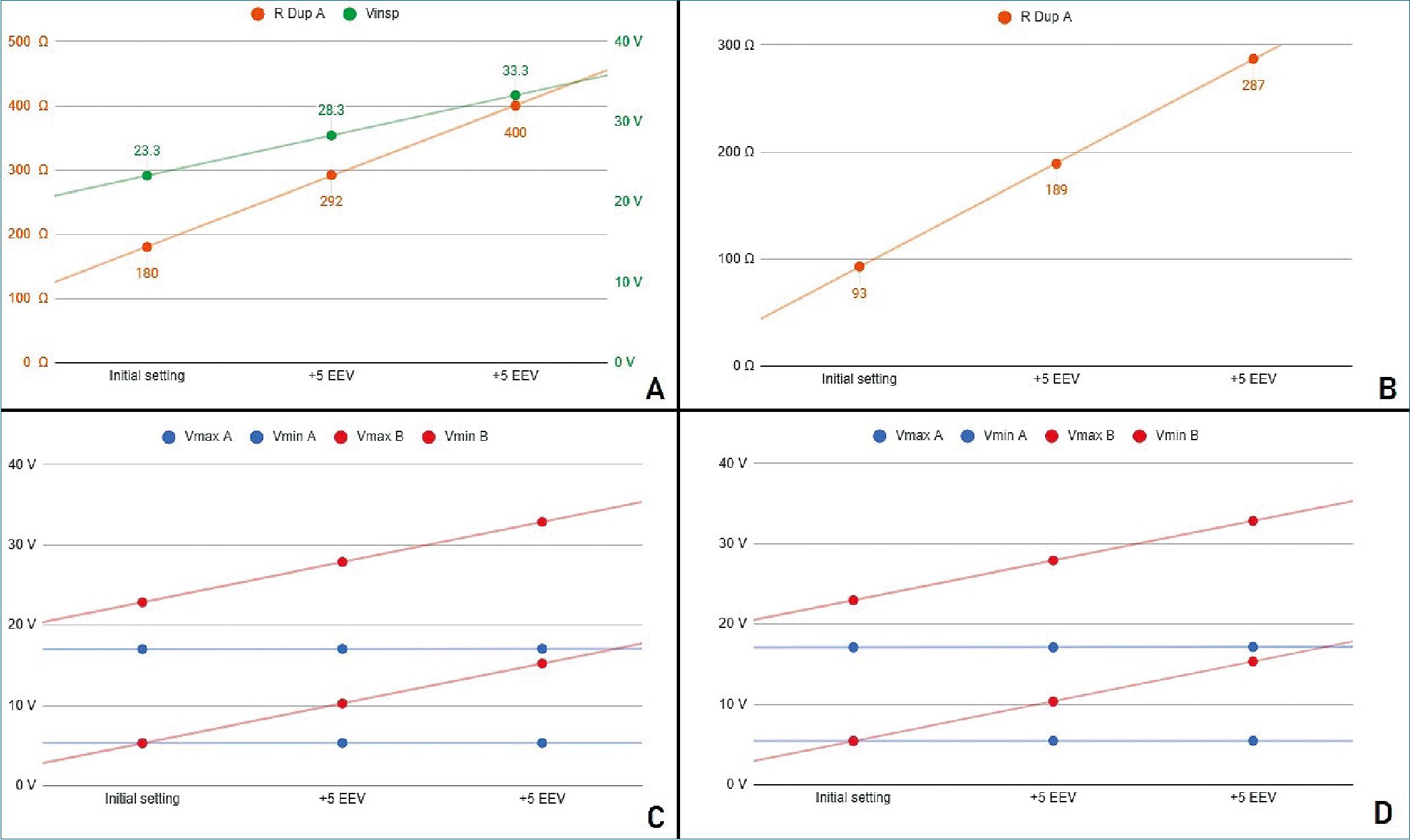
Figure 3. Stage 2 simulation A. PCV mode. In green, power source voltage; in orange DuplicAR® resistance of RC circuit A; B. VCV mode. DuplicAR resistance of RC circuit A in each step; C. Voltages registers under PCV mode; D. Voltages registers under VCV mode.
-
Stage 2
Both simulated subjects are the same size, resulting in the same charge requirement (350 pC). Since RC circuit B presents a reduced capacitance, it requires a greater driving voltage than RC circuit A (for circuit A; for B). To achieve these voltage differences in PCV mode, the inspiratory voltage needs to be first configured in the ventilatory system to guarantee the charge to the RC circuit with the lowest capacitance and then to be de- creased in the other RC circuit using the inspiratory resistance of the DuplicAR® device (Figure 3A, case I).
In VCV mode, total configured charge is delivered by the ventilatory system to the group, but its distribution results asymmetric regarding differences in RC circuits characteristics. The precise charge distribution for each subject needs to be regulated by the inspiratory resistance regulators of DuplicAR® device in the patient with greater capacitance (Figure 3B, case I).
In this way, with a single ventilator configuration, different driving voltages are established. In both ventilatory modes (PCV and VCV) it is possible to modify the EEV of a RC circuit with- out compromising its driving voltage or modifying the other circuit’s parameters (Figures 3C and 3D).
With each increase in EEV, the driving voltage is preserved. In PCV mode, this is accomplished by increasing the inspiratory voltage of the ventilator system to maintain the driving voltage of the RC circuit with an increased EEV. Accurate driving voltage in RC circuit A is modulated by the inspiratory resistance of the DuplicAR® device, preventing excessive voltages. In VCV mode the total charge is set. Since EEV of RC circuit B increases, the inspiratory resistance of RC circuit A needs to be adjusted in order to achieve an adequate charge distribution.
-
Stage 3
It is important to highlight the disparity of voltage differences needed to ensure the target charge of each RC circuit. Capacitor A requires a driving voltage of 11.7 V to reach 350 pC (350 pC/pF = 11.7 V) and capacitor C requires 19.6 V to achieve 196 pC (196 pC/10 pF = 19.6 V), reflecting the differ- ence in their sizes and capacitances. In both cases the RC units receive the target charge of 7 pC kg-1. To achieve these voltage differences in PCV mode, the inspiratory voltage needs to be first configured in the ventilatory system to ensure the charge to the RC circuit with the lowest capacitance and then to be decreased in the other using the inspiratory resistance of the DuplicAR® device (Figure 4A, case I).
In VCV mode, total configured charge is delivered by the ventilatory system to the group, but its distribution results asymmetric regarding differences in RC circuits characteristics.
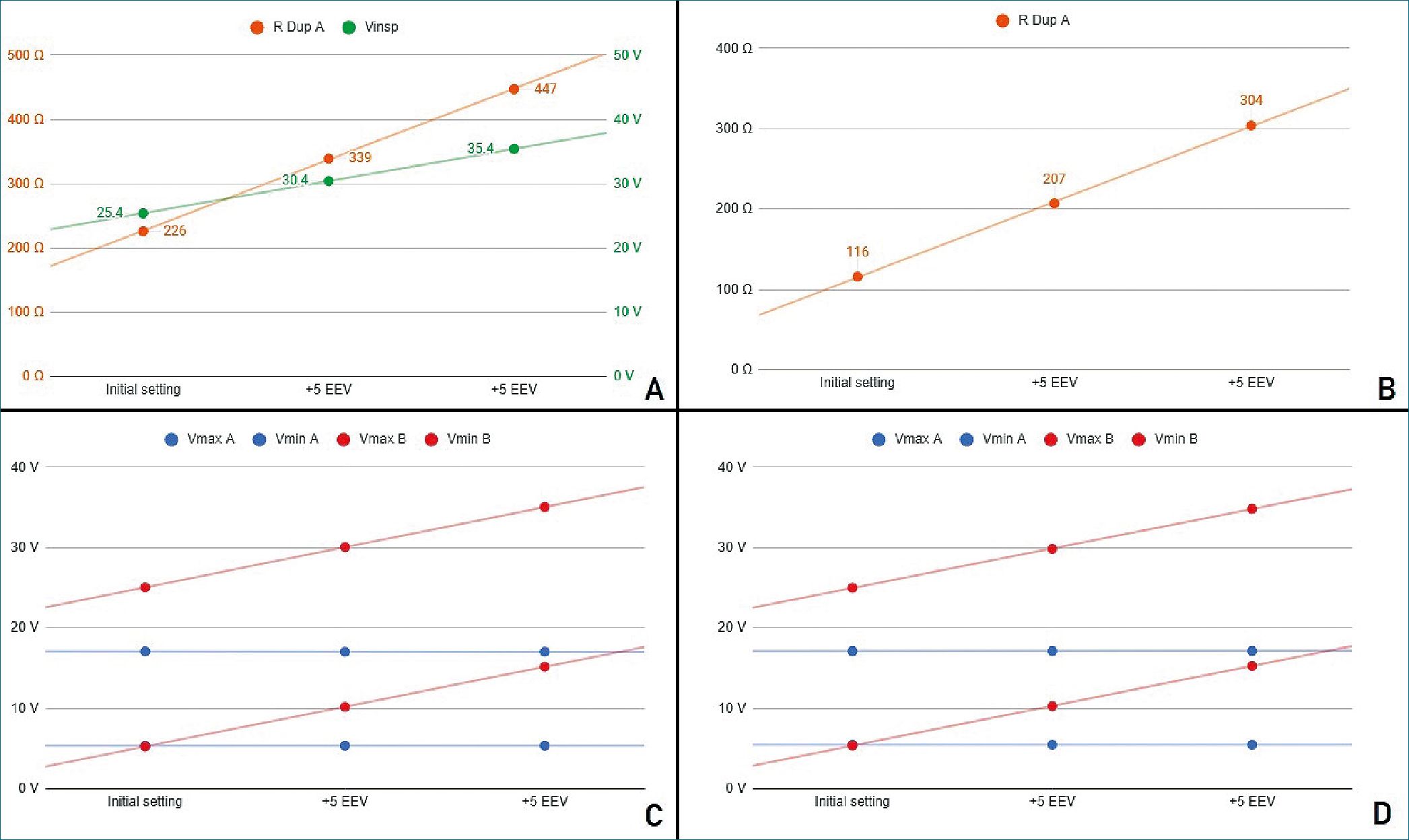
Figure 4. Stage 3 simulation A. PCV mode. In green, power source voltage; in orange DuplicAR® resistance of RC circuit A; B. VCV mode. DuplicAR resistance of RC circuit A in each step; C. Voltages registers under PCV mode; D. Voltages registers under VCV mode.
The precise charge distribution for each RC circuit needs to be regulated by the inspiratory resistance controllers of the DuplicAR® device in the unit with greater capacitance (Figure 4B, case I).
In this way, with a single ventilator configuration, different driving voltages are established. In both ventilatory modes (PCV and VCV) it is possible to modify the EEV of a RC circuit without compromising its driving voltage or modifying the other circuit’s parameters (Figures 4C and 4D).
With each increase in EEV, the driving voltage is preserved. In PCV mode, this is accomplished by increasing the inspiratory voltage of the ventilator system to maintain the driving voltage of the RC circuit with an increased EEV. Accurate driving voltage in capacitor A is modulated by the inspiratory resistance of the DuplicAR® device, preventing excessive voltages. In VCV mode, total charge is set. Since the EEV of capacitor C increases, the inspiratory resistance of RC circuit A needs to be adjusted in order to achieve an adequate charge distribution.
-
Discussion
Understanding complex systems can be facilitated by using reductionist models which describe the behavior of variables in simpler ways. With this approach, mechanical ventilation can be represented by an electrical model[12]. By simplifying the respiratory system to an electrical model, we seek to find the relationship between variables of interest (pressure, volume, flow, etc.).
In our simulation system, each variable in mechanical ventilation has an electrical equivalent. The variables pressure, volume, flow, resistance and compliance are considered equivalent to voltage, charge, current, electrical resistance and capacitance, respectively. On the other hand, the components of the ventilatory circuit, such as tubes and valves, are considered equivalent to cables and diodes, respectively.
According to the equation of motion, pressure required to drive gas into the airways and inflate the lungs is caused by the resistive and elastic elements. Lung inflation pressure (Paw) can be expressed:
Paw = F x Raw + Vt/Crs + PEEP
Where F is flow, Raw airway resistance, Vt tidal volume, PEEP positive end-expiratory pressure and Crs compliance of the respiratory system. Using the electrical analog of this equation, the respiratory system can be modeled as an RC circuit, with an electrical resistance connected in series with a capacitor. In these types of circuits, the total voltage (AV) should be equal to the sum of voltages on the resistor and capacitor. In this way, the equation that describes the behavior of the system is now:
AV = I x R + q/C + EEV
Where AV is the potential difference applied to the system, I is the current that flows, R the electrical resistance, q the charge of the capacitor, C the capacitance and EEV is the end-expiratory voltage.
Several studies have addressed the issue of multiple ventilation[13],[14]. In most of these studies, there is no capacity to safely and effectively control the ventilatory parameters for each patient. The only scenario in which adequate combined ventilation is achieved without the need to intervene is in the presence of two identical subjects (same size and compliance) and with the same PEEP. COVID-19 patients’ ventilator requirements can be quite disparate, and also can change over time. When changes in compliance and/or resistance occur, there can be rapid and substantial alteration in the Vt delivered to the other patient.
These types of problems have generated much criticism of combined ventilation and have even discouraged its use. However, in the United States, the Food and Drug Administration has authorized the use of modified ventilator devices and breathing circuits to increase surge capacity (https://www.fda. gov/regulatory-information/search-fda-guidance-documents/ enforcement-policy-ventilators-and-accessories-and-other-re- spiratory-devices-during-coronavirus). This type of modification can be carried out with the DuplicAR® device, allowing the individualization of the ventilatory parameters.
Similar modifications to the ventilators have been made and tested with similar results to those shown here. Herrmann and coworkers [15] describe the use of PEEP valves, adjustable constrictions and pressure-relief valves to adapt a ventilator for simultaneous ventilation of two patients. The results of their studies, both in computer simulation and in vitro experimentation, are comparable with those obtained in the present work. The authors do not recommend the “naive” use of combined ventilation as it is particularly dangerous, but they do suggest considering it if devices are used to allow individualization.
Although several works use in silico models to simulate different combined ventilation scenarios, most are based on computational models of mechanically ventilated lungs[16],[17]. Given the analogy between mechanical and electrical systems, we use a simulated electrical model to run different scenarios. The simulations allow future operators an opportunity to understand the systems, manipulate them in real time and push them to the limit without compromising patients.
The DuplicAR® system proved to be useful in the ventilation of animals in a previous pilot work (in vivo testing) [8]. Similarly, the device was also evaluated in test lungs (in vitro testing)[18] with results equivalent to those of the present simulation (in silico testing).
The present work shows the performance of the DuplicAR® device in an electronic computer-based model. With this tool it is possible to generate “cleaner” scenarios and even push the device to the limit safely, quickly and with practically no cost.
The results of simulations, transferred to mechanical ventilation, show that it is possible to ventilate two subjects with different sizes and/or compliances and/or PEEP requirements adequately. According to the model, this could be achieved by adjusting the Pi of the ventilator or the PEEP valve of each subject or the inspiratory resistances of the DuplicAR® device. The type and magnitude of the adjustment in each component of the model depend on the ventilatory mode and the characteristics of the subjects.
While these simulations show that the ventilatory goals can be achieved in any of the ventilatory modes, PCV has advantages over VCV. In PCV, the driving pressure can be established and delivered during the inspiratory cycle to both subjects, regardless of their RC characteristics, that is, of their airway resistance and pulmonary compliance. In this mode, there is certainty about the Pi of each subject. As a general limitation of this ventilation mode, it is not possible to know the volume that will be delivered to the system or to each subject. On the other hand, in VCV mode, a total volume to be delivered must be established, that is, the sum of the Vt of both subjects. This volume is not delivered equally to each subject. It is rather dis- tributed among them according to their RC characteristics, and there is no control over the Pi and the Vt.
Although not demonstrated in our simulation, another advantage of PCV mode is that changes in RC characteristics of one subject (i.e. dynamical compliance variability, endotracheal tube obstruction, etc.) do not affect pressurization of the system, and therefore have no consequences on the contralateral subject. On the contrary, in VCV mode, changes in resistance or compliance in one subject directly impact the other subject.
In the model, a similar phenomenon is observed when modifying the EEV in one RC circuit. By increasing the EEV in VCV, the contralateral RC circuit receives a greater charge, since it is necessary that the inspiratory lines reach greater voltage to al- low charge to be delivered to the RC circuit with greater EEV. In other words, greater proximal voltage is needed to generate a potential difference that allows charge entry into the RC circuit. This is accomplished at the expense of increasing the charge on the capacitor with no modification of the EEV. In contrast, in PCV, the increase in a RC circuit EEV (without modifying the power source) only affects the unit in which the modification was made. As in the model the changes in EEV do not affect capacitance, the driving voltage is lower and therefore the charge received. This behavior of the electric model to changes in the EEV is consistent with the results of the mechanical model[18].
Additionally, it should be considered that PCV spontaneously compensates for the compliance added to the system by the tubing, which in combined ventilation is expected to contain twice the volume compared to single (conventional) ventilation. This must be manually compensated in VCV mode by adding an extra volume to the total charge delivered by the ventilator. According to the results of the simulations of this study, the most efficient and safest ventilatory mode to use DuplicAR® is PCV.
Although in the theoretical field and in in vitro experimentation, combined ventilation seems promising as a life-saving strategy, we do not yet have large-scale studies that demonstrate its benefit in terms of morbidity and mortality. The decision to use combined ventilation should be made on a case-by- case basis, basing the decision on the best ethical and scientific principles[19]. The medical personnel in charge must obtain the informed consent of the patients and acknowledge the operation of this ventilation strategy in detail to maximize its success.
-
Limitations
The present study has limitations. A first observation is that the capacitance for each capacitor in the electrical model is constant. Thus, we assume that ventilation takes place in the region between the lower and upper inflection points of the compliance curve, where it behaves like a linear function. According to this, capacitance is constant, independent of the voltages applied. In clinical practice this would imply that regardless of the pressure applied, the relationship between a volume and a pressure differential would behave as a constant. This assumption may not be real in mechanical ventilation scenarios. In addition, when the simulation takes place at higher voltages, the gas compression that would occur at these simulated pressures was not modeled in the electrical simulation.
As a second limitation, the precise titration of the inspiratory resistance of each patient achieved in the electrical model can hardly be transferred to the real model.
In our electrical model, the ability of the ventilator to “pressurize” the system is not an issue, as the voltage or current source has unlimited capacity. In real life, ventilators may be limited to provide pressurization to larger systems with greater absolute compliances. The electrical model does not consider the greater compliance of a system with larger tubing connections. This would produce a “volume steal” in VCV mode, which was not contemplated in our simulations.
Finally, the objective of the simulated mechanical and electrical models is to represent, in a reductionist way, the interaction between variables in a combined mechanical ventilation scenario. Such models do not take into account other aspects that should be considered in clinical practice, such as hemodynamic status, quality of gas exchange, and the possibility of in- advertent spontaneous ventilation in patients under combined ventilation.
-
Conclusions
The electrical computer-based simulations are a safe, pedagogical, and effective tool for understanding combined ventilation. In this model, the DuplicAR® system was shown to be effective in precisely controlling the distribution of charge between capacitors, even in scenarios with different capacitance and with different end-expiratory voltages. These simulations reinforce the fact that it is possible to individualize the ventilatory parameters in two patients connected to a single ventilator.
-
Supplementary Material
In the supplementary material, additional tables are attached with the data used to construct the graphs for each stage. Additionally, two video clips running the simulations in both PCV and VCV are included as supplementary material. The simulated values are not strictly those used during the experimental protocols. The electrical circuit used and the morphology of the graphs obtained are shown. A web page is also add- ed where the code can be found to reproduce any simulation carried out, with its initial conditions and the diagrams of the circuits used.
Acknowledgements: We acknowledge the preprint service of medRxiv. A preprinted version of this work can be found at: https://doi.org/10.1101/2021.01.17.21249912 (2021).
Diego Riva acknowledges the support of the National Uni-
versity of La Plata, CONICET and IP-COVID (Fundación Bunge y Born-Agencia I+D+i) in his projects.
Conflicts of Interest: Lugones I. is the trademark holder and the author of the patent application.
-
References
1. Ranney ML, Griffeth V, Jha AK. Critical Supply Shortages – The Need for Ventilators and Personal Protective Equipment during the Covid-19 Pandemic. N Engl J Med. 2020 Apr;382(18):e41. https://doi.org/10.1056/NEJMp2006141 PMID:32212516
2. Maves RC, Downar J, Dichter JR, Hick JL, Devereaux A, Geiling JA, et al.; ACCP Task Force for Mass Critical Care. Triage of Scarce Critical Care Resources in COVID-19 An Implementation Guide for Regional Allocation: An Expert Panel Report of the Task Force for Mass Critical Care and the American College of Chest Physicians. Chest. 2020 Jul;158(1):212–25. https://doi.org/10.1016/j.chest.2020.03.063 PMID:32289312
3. Christian MD, Devereaux AV, Dichter JR, Rubinson L, Kissoon N. Care of the Critically Ill and Injured During Pandemic and Disasters: CHEST Consensus Statement. Chest. 2014;146(4 Suppl):8S–34S. https://doi.org/10.1378/chest.14-0732 PMID:25144202
4. Sommer DD, Fisher JA, Ramcharan V, Marshall S, Vidic DM. Improvised automatic lung ventilation for unanticipated emergencies. Crit Care Med. 1994 Apr;22(4):705–9. PMID:8143481
5. Neyman G, Irvin CB. A single ventilator for multiple simulated patients to meet disaster surge. Acad Emerg Med. 2006 Nov;13(11):1246–9. https://doi.org/10.1197/j.aem.2006.05.009 PMID:16885402
6. Paladino L, Silverberg M, Charchaflieh JG, Eason JK, Wright BJ, Palamidessi N, et al. Increasing ventilator surge capacity in disasters: ventilation of four adult-human-sized sheep on a single ventilator with a modified circuit. Resuscitation. 2008 Apr;77(1):121–6. https://doi.org/10.1016/j.resuscitation.2007.10.016 PMID:18164798
7. The Society of Critical Care Medicine (SCCM), American Association for Respiratory Care (AARC), American Society of Anesthesiologists (ASA), Anesthesia Patient Safety Foundation (APSF), American Association of Critical-Care Nurses (AACN), and American College of Chest Physicians (CHEST). Joint Statement on Multiple Patients Per Ventilator SCCM, AARC, ASA, APSF, AACN, and CHEST Share Unified Message. 2020.
8. Lugones I, Giambastiani RO, Robledo O, Marcos M, Mouly J, Gallo A, et al. “A New Medical Device to Provide Independent Ventilation to Two Subjects Using a Single Ventilator: Evaluation in Lung-Healthy Pigs”, Anesthesiology Research and Practice, vol. 2020, Article ID 8866806, 6 pages, 2020. https://doi.org/10.1155/2020/8866806.
9. Monitoring respiratory mechanics in mechanically ventilated patients. Available at: https://www.hamilton-medical.com/en_US/News/Newsletter-articles/Article~2018-04-30~Monitoring-respiratory-mechanics-in-mechanically-ventilated-patients~6e39d4bb-1ab7-4c46-bc18-83f3e77897f9~.html [Accessed June 4, 2021].
10. Powner DJ, Eross B, Grenvik A. Differential lung ventilation with PEEP in the treatment of unilateral pneumonia. Crit Care Med. 1977 Jul-Aug;5(4):170–2. https://doi.org/10.1097/00003246-197707000-00002 PMID:326483
11. Falstad educational applets. http://www.falstad.com/mathphysics.html [Accessed June 4, 2021].
12. Ghafarian P, Jamaati H, Hashemian SM. A Review on Human Respiratory Modeling. Tanaffos. 2016;15(2):61–9. PMID:27904536
13. Branson RD, Blakeman TC, Robinson BR, Johannigman JA. Use of a single ventilator to support 4 patients: laboratory evaluation of a limited concept. Respir Care. 2012 Mar;57(3):399–403. https://doi.org/10.4187/respcare.01236 PMID:22005780
14. Beitler JR, Kallet R, Kacmarek R, Branson R, Brodie D, Mittel AM, et al. Ventilator sharing protocol: Dual-patient ventilation with a single mechanical ventilator for use during critical ventilator shortages. Available at: https://www.gnyha.org/wp-content/uploads/2020/03/Ventilator-Sharing-Protocol-Dual-Patient-Ventilation-with-a-Single-Mechanical-Ventilator-for-Use-during-Critical-Ventilator-Shortages.pdf
15. Herrmann J, Fonseca da Cruz A, Hawley ML, Branson RD, Kaczka DW. Shared Ventilation in the Era of COVID-19: A Theoretical Consideration of the Dangers and Potential Solutions. Respir Care. 2020 Jul;65(7):932–45. https://doi.org/10.4187/respcare.07919 PMID:32376612
16. Webb JB, Bray A, Asare PK, Clipp RB, Mehta YB, Penupolu S, et al. Computational simulation to assess patient safety of uncompensated COVID-19 two-patient ventilator sharing using the Pulse Physiology Engine. PLoS One. 2020 Nov;15(11):e0242532. https://doi.org/10.1371/journal.pone.0242532 PMID:33237927
17. Kheyfets VO, Lammers SR, Wagner J, Bartels K, Piccoli J, Smith BJ. PEEP/ FIO2 ARDSNet Scale Grouping of a Single Ventilator for Two Patients: Modeling Tidal Volume Response. Respir Care. 2020 Aug;65(8):1094–103. https://doi.org/10.4187/respcare.07931 PMID:32712582
18. Lugones I, Ramos M, Biancolini MF, Orofino Giambastiani R. Combined Ventilation of Two Subjects with a Single Mechanical Ventilator Using a New Medical Device: An In Vitro Study. Anesthesiol Res Pract. 2021 Feb;2021:6691591. https://doi.org/10.1155/2021/6691591 PMID:33628233
19. Cook DC. Implementing shared ventilation must be scientific and ethical, or it risks harm. Br J Anaesth. 2020 Jul;125(1):e181–3. https://doi.org/10.1016/j.bja.2020.04.061 PMID:32416993